What is Torque?
 |
According to Webster: |
Basic Torque Formula
L (length) x F (force) = T (torque)
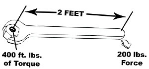
Example: A two foot lever at a right angle to the fastener with 200 pounds at the end will produce
400 foot/pounds of torque.
Torque Formula: L x F = T
|
|
|
What are we trying to achieve with a torque wrench?
Answer: Proper Clamping Force |
|
|
Torque and Clamping Force
Controlling the torque applied in tightening threaded fasteners is the most commonly used method for the application of clamping force. There are many factors which may affect the relationship between torque and clamping force of threaded fasteners. Some of these are: the type of lubricant used on the threads, the material from which the bolt and nut are made, the type of washers used, the class and finish of threads and various other factors. It is not possible to establish a definite relationship between torque and clamping force which will be applicable for all conditions.
Torque Versus Clamping Force
Only a small part of the torque applied to a fastener contributes to clamping force. The remaining, as much as 90% of the total applied torque, is used to overcome friction under the fastener head (or between nut and washer) and friction in thread engagement.
TORQUE
Head Friction:
45% - 55%
Thread Friction:
35% - 45%
Clamping Force:
10%
|
TORQUE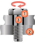 1. Head Friction
2. Thread Friction
3. Clamping Force
 |
|
|
|
|
> return to top
Torque Wrench Safety
These precautions should always be taken when using any torque wrench to avoid possible injury:
|
|
|
> return to top
Torque Conversion
|
Easy-to-use Torque
Conversion Table
To
Convert
From |
To |
Multiply
by |
| in. oz. |
in. lb. |
0.0625 |
| in. lb. |
in.oz. |
16 |
| in. lb. |
ft.lb. |
0.08333 |
| in. lb. |
cmkg |
1.1519 |
| in. lb. |
mkg |
0.011519 |
| in. lb. |
Nm |
0.113 |
| in. lb. |
dNm |
1.13 |
| ft. lb. |
in. lb. |
12 |
| ft. lb. |
mkg |
0.1382 |
| ft. lb. |
Nm |
1.356 |
| dNm |
in. lb. |
0.885 |
| dNm |
Nm |
0.10 |
| Nm |
dNm |
10 |
| Nm |
cmkg |
10.2 |
| Nm |
mkg |
0.102 |
| Nm |
in. lb. |
8.85 |
| Nm |
ft. lb. |
0.7376 |
| cmkg |
in. lb. |
0.8681 |
| cmkg |
Nm |
0.09807 |
| mkg |
in. lb. |
86.81 |
| mkg |
ft. lb. |
7.236 |
| mkg |
Nm |
9.807 |
|
|
|
|
|
Common Torque Abbreviations
Foot Pounds – ft. lbs.
Inch Pounds – in. lbs.
Inch Ounces – in. ozs.
Newton Meter – Nm
Centi-Newton Meter – cNm
Meter Kilogram – Mkg
|
Torque Conversion Calculators
To convert torque values for other units, click on the unit you are starting with below and a popup window calculator will provide you a quick way to make the conversions:
|
|
|
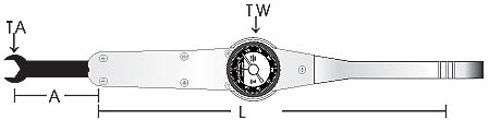
Use of Adapter
Formula: |
|
|
Length (L) = |
Effective length of the wrench as described below.
|
Dial Wrenches = |
The measured distance from the center of the square drive to the center ring or notch on the handle.
|
Micrometer Wrenches = |
The measured length from the center of the square drive to the center of the handle, with the wrench set at the desired torque reading.
|
Desired Torque (TA) = |
The torque value designated for the fastener with or without an adapter.
|
Added Length of Adapter (A) = |
The measured length from the center of the adapter drive to the center of the wrench square drive.
|
New Setting (TW) = |
The torque setting on the wrench allowing for the added length of the adapter. This reading will be lower than the desired torque.
|
Example: |
250 ft. lb. Dial Wrench using a 2” long crowfoot adapter
L = Effective Length: 18.75”
Desired Torque = 250 ft. lb.
Length of Adapter = 2” |
Result: |
18.75" x 250 ft. lb.
18.75" + 2" |
= Pull Wrench to 226 ft. lb. |
|
> return to top
Indicated Value vs. Full Value
|
| Issues to consider when selecting an electronic torque tester: |
|
|
1 Accuracy: Generally there are two ways of stating accuracy:
A. % of full-scale deflection or FSD
B. % of indicated value or reading
The following example will show the difference between the two methods:
|
Case 1 - Assume you have a 100 ft. lb. tester (maximum), and that the stated accuracy is +/- 0.5% of full scale.
At 100 ft. lb. +/- 0.5% full scale error = .5 ft, lb. This represents the “best case” error of the system. However, when a lower range is utilized, this .5 ft-lb becomes more significant. That is, on the same 100 ft. lb. tester;
at 50 ft. lb. - .5 ft. lb. error = 1% accuracy
at 10 ft, lb. - .5 ft. lb. error = 5% accuracy
at 1 ft. lb. - .5 ft. lb. error = 50% accuracy
Therefore, what looks to be a good accuracy reading at full-scale actually translates into substantial error at the low range of the tester.
|
|
|
Case 2 - Assume you have a 100 ft. lb. tester (maximum), and that the stated accuracy is +/- 0.5% of indicated value.
at 100 ft. lb. - .5% error .5 ft. lb.
at 50 ft. lb. - .5 % error .25 ft. lb.
at 10 ft. lb. - .5% error .05 ft. lb.
As can be seen by the above examples, error as related to full-scale value increases significantly as you go lower in the range, while error as related to indicated value stays constant throughout the useful range of the tester.
|
|
|
2 Range: Generally when manufacturers advertise % error of full-scale, their useful ranges will be advertised from zero to full-scale. That is, +/- 0.5% accurate (full-scale) from 0-100 ft. lb. This is interesting because at zero ft. lb., the system is only accurate to within +/- 0.5 ft. lb. Basically, error goes to infinity at zero.
|
|
|
Furthermore, transducers which are used to convert the mechanical torque into an electrical signal may become inconsistent below 10% of full-scale deflection.
It is for the above stated reason that systems which have accuracy as related to indicated value should state the useful range to be 10% to 100% of the tester range.
Therefore, if a tester has 100 ft. lb. maximum range, it should not be used at less than 10 ft. lbs. if the desired accuracy is needed.
It is CDI’s belief that in order to be completely honest to the customer, accuracy should always be stated as a percent of indicated value and the useful range should correspond to that stated accuracy. This will prevent the user from having to calculate what the
real error is at any given range.
3 Circuitry: There are two basic ways of measuring the output of a torque transducer.
- Analog (non-microprocessor based pure analog)
- Digital (microprocessor based plus analog input)
Without in-depth explanations of these two systems, the following advantages of having digital circuitry are well known throughout the electronics industry.
- Digital systems are economical, flexible and compact.
- Digital systems improve reliability in the face of hardware imperfections.
- Digital systems allow the ability to make logical decisions, carry out digital computations (unlimited unit conversion) and store the results in memory.
Basically, full digital systems are computer controlled. It is important that the terms “digital display” or “digital memory” do not necessarily mean that the system has full digital circuitry. |
|
|
> return to top
Bolt Torque Specifications
|
Bolt Torque Charts
These charts show suggested maximum torque values for threaded products and are intended only as a guide. Always refer to the manufacturers recommended torque values if possible. CDI Torque Products is not responsible for any application of torque or it's consequences as a result of using this chart. Use at your own risk! |
|
|
|
|
Bolt Size |
18-8
Stainless
Steel |
Brass |
Aluminum
2024-T4 |
316
Stainless
Steel |
Nylon |
| INCH POUNDS |
2 - 56 |
2.5 |
2.0 |
1.4 |
2.6 |
0.44 |
4 - 40 |
5.2 |
4.3 |
2.9 |
5.5 |
1.19 |
4 - 48 |
6.6 |
5.4 |
3.6 |
6.9 |
|
6 - 32 |
9.6 |
7.9 |
5.3 |
10.1 |
2.14 |
6 - 40 |
12.1 |
9.9 |
6.6 |
12.7 |
|
8 - 32 |
19.8 |
16.2 |
10.8 |
20.7 |
4.30 |
8 - 36 |
22.0 |
18.0 |
12.0 |
23.0 |
|
10 - 24 |
22.8 |
18.6 |
13.8 |
23.8 |
6.61 |
10 - 32 |
31.7 |
25.9 |
19.2 |
33.1 |
8.20 |
1/4" - 20 |
75.2 |
61.5 |
45.6 |
78.8 |
16.00 |
1/4" - 28 |
94.0 |
77.0 |
57.0 |
99.0 |
20.80 |
5/16" - 18 |
132.0 |
107.0 |
80.0 |
138.0 |
34.90 |
5/16" - 24 |
142.0 |
116.0 |
86.0 |
147.0 |
|
3/8" - 16 |
236.0 |
192.0 |
143.0 |
247.0 |
|
3-8" - 24 |
259.0 |
212.0 |
157.0 |
271.0 |
|
7/16" - 14 |
376.0 |
317.0 |
228.0 |
393.0 |
|
7/16" - 20 |
400.0 |
357.0 |
242.0 |
418.0 |
|
1/2" - 13 |
517.0 |
422.0 |
313.0 |
542.0 |
|
1/2" - 20 |
541.0 |
443.0 |
328.0 |
565.0 |
|
9/16" - 12 |
682.0 |
558.0 |
413.0 |
713.0 |
|
9/16" - 18 |
752.0 |
615.0 |
456.0 |
787.0 |
|
5/8" - 11 |
1110.0 |
907.0 |
715.0 |
1160.0 |
|
5/8" - 18 |
1244.0 |
1016.0 |
798.0 |
1301.0 |
|
3/4" - 10 |
1530.0 |
1249.0 |
980.0 |
1582.0 |
|
3/4" - 16 |
1490.0 |
1220.0 |
958.0 |
1558.0 |
|
7/8" - 9 |
2328.0 |
1905.0 |
1495.0 |
2430.0 |
|
7/8" - 14 |
2318.0 |
1895.0 |
1490.0 |
2420.0 |
|
1" - 8 |
3440.0 |
2815.0 |
2205.0 |
3595.0 |
|
1"- 14 |
3110.0 |
2545.0 |
1995.0 |
3250.0 |
|
Bolt
Size
Inches |
Coarse
Thread/
inch |
SAE 0-1-2
74,000 psi
Low Carbon
Steel |
SAE Grade 3
100,000 psi
Med Carbon
Steel |
SAE Grade 5
120,000 psi
Med. Carbon
Heat T. Steel |
SAE Grade 6
133,000 psi
Med. Carbon
Temp. Steel |
SAE Grade 7
133,000 psi
Med. Carbon
Alloy Steel |
SAE Grade 8
150,000 psi
Med Carbon
Alloy Steel |
| FOOT POUNDS |
1/4 |
20 |
6 |
9 |
10 |
12.5 |
13 |
14 |
5/16 |
18 |
12 |
17 |
19 |
24 |
25 |
29 |
3/8 |
16 |
20 |
30 |
33 |
43 |
44 |
47 |
7/16 |
14 |
32 |
47 |
54 |
69 |
71 |
78 |
1/2 |
13 |
47 |
69 |
78 |
106 |
110 |
119 |
9/16 |
12 |
69 |
103 |
114 |
150 |
154 |
169 |
5/8 |
11 |
96 |
145 |
154 |
209 |
215 |
230 |
3/4 |
10 |
155 |
234 |
257 |
350 |
360 |
380 |
7/8 |
9 |
206 |
372 |
382 |
550 |
570 |
600 |
1 |
8 |
310 |
551 |
587 |
825 |
840 |
700 |
1-1/8 |
7 |
480 |
872 |
794 |
1304 |
1325 |
1430 |
1-1/4 |
7 |
375 |
1211 |
1105 |
1815 |
1825 |
1975 |
1-3/8 |
6 |
900 |
1624 |
1500 |
2434 |
2500 |
2650 |
1-1/2 |
6 |
1100 |
1943 |
1775 |
2913 |
3000 |
3200 |
1-5/8 |
5.5 |
1470 |
2660 |
2425 |
3985 |
4000 |
4400 |
1-3/4 |
5 |
1900 |
3463 |
3150 |
5189 |
5300 |
5650 |
1-7/8 |
5 |
2360 |
4695 |
4200 |
6980 |
7000 |
7600 |
2 |
4.5 |
2750 |
5427 |
4550 |
7491 |
7500 |
8200 |
|
|
|
|
|
|
|
|
|